ULN Gas Valve Characteristics & Important Information
ULN Gas Valve Characteristics, Adjustments & Important Information
IMPORTANT: ENSURE that the furnace gas valve is not to be subjected to high gas line supply pressures.
DISCONNECT the furnace and its individual manual gas stop from the gas supply piping during any pressure testing that exceeds ½ PSIG. (3.48 kPa).
Natural gas supply pressure must be 6” to 10.5” w.c. This pressure must be maintained with all other gas-fired appliances in operation.
The minimum gas supply pressure to the gas valve for proper furnace input adjustments is 6” w.c. for natural gas, however 7” is recommended. This furnace is equipped with a gas pressure switch that will not allow operation below 5” w.c. of inlet gas pressure.
This furnace has a 24-volt gas valve. It has ports for measuring supply and manifold gas pressure. The valve body contains a pressure regulator to maintain proper manifold gas pressure.
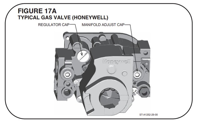
A control switch is on the valve body. It can be set to only the “ON” or “OFF” positions. The gas valve is a slow-opening valve. See Figures 17A and 17B.
When energized, it takes 2 to 3 seconds to fully open.
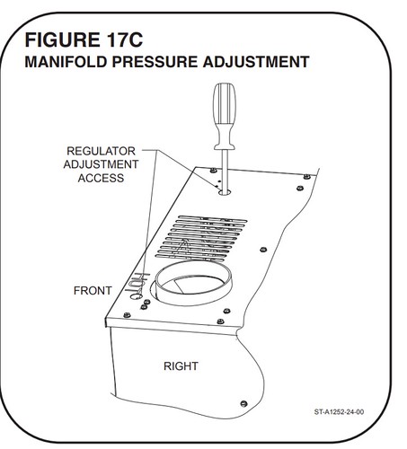
To adjust manifold pressure, insert screwdriver in top plate access holes. See Figure 17C
Setting Gas Pressures
The maximum gas supply pressure to the furnace must not exceed 10.5” w.c. natural gas. The minimum supply gas pressure to the gas valve should be 59 w.c. natural gas. A properly calibrated manometer is required for accurate gas pressure measurements.
Supply Gas Pressure Measurement
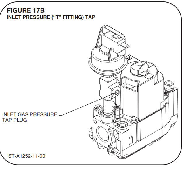
An inlet pressure tap is on the input side of the gas valve located in a “T” between the gas valve and the gas pressure switch (Figure 17B).
1. With gas shut off to the furnace at the manual gas valve outside the unit, remove the inlet pressure tap plug from the tee.
2. Connect a manometer to the pressure tap.
3. Turn on the gas supply and operate the furnace and all other gas-fired units on the same gas line as the furnace.
4. Note or adjust the line gas pressure to give: 69 - 10.59 w.c. for natural gas.
5. Shut off the gas at the manual gas valve and remove the manometer and hose.
6. Replace the pressure tap plug before turning on the gas.
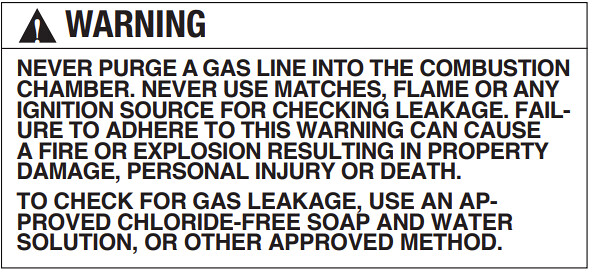
7. Turn on the gas supply and check for gas leaks using an approved leak detector. DO NOT use a flame of any kind to check for leaks. Repair any leaks and repeat.
If the supply gas line pressure is above these ranges, a high pressure in line gas regulator may be required. Consult local gas utility.
If supply gas line pressure is below these ranges, either remove any restrictions in the gas supply piping or enlarge the gas pipe.
NOTE: This unit is equipped with a gas pressure switch that will not allow operation below 59 w.c. of inlet gas pressure.
NOTE: Pre-mix Ultra Low NOx burners (unlike conventional burners) require careful attention to purge gas lines before start-up. It is important to remove as much air from the gas line as possible before attempting to light. It may require multiple trials for ignition before successful initial ignition.
Manifold Gas Pressure Measurement
Natural gas manifold pressure should be 3.5” w.c. Only small variations in gas pressure should be made by adjusting the pressure regulator.
1. With the gas to the unit shut off at the manual gas valve, remove the MANIFOLD pressure tap plug.
2. Connect a manometer to this pressure tap.
3. Turn on the gas supply and operate the furnace (apply a heat call).
4. Note or adjust the manifold gas pressure to give: 3.59 w.c. for natural gas (+/- .39 w.c.).
5. To adjust the pressure regulator, remove the regulator cap. (See Figures 17A, 17B and 17C.)
6. Turn the adjustment screw clockwise to increase pressure, or counterclockwise to decrease pressure.
7. Securely replace the regulator cap.
8. Shut off gas at the manual gas valve and remove the manometer and hose.
9. Replace the pressure tap plug before turning on the gas.
10. Turn on the gas supply and apply a heat call to the furnace then check for gas leaks using an approved leak detector. Do NOT use a flame of any kind to check for leaks. Repair any leaks and repeat.